SPLIT SET ANCHORS

7

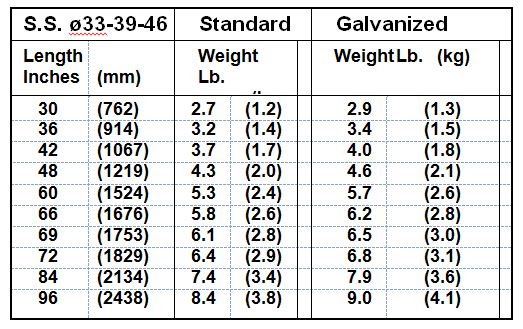
Specifications and performance

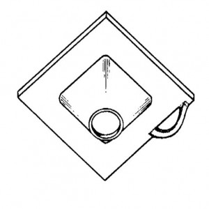
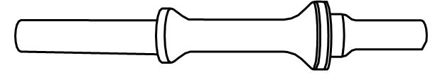
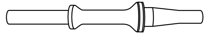
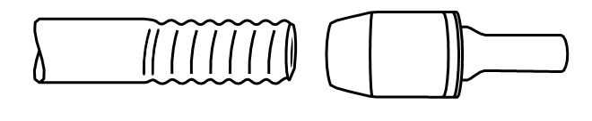
The Split Set stabilizer is a slotted steel tube, with one end tapered for easy insertion into a drill hole. The other end has a welded ring flange to hold the bearing plate.

The stabilizer is inserted into a hole slightly smaller in diameter than the tube, using a simple driver tool fitted to the drill. As the tube enters, its diameter is compressed and the slot partially closes. This exerts radial forces along the length of contact with the rock, providing the friction which holds the rock together. The driving force of the drill actively loads the bearing plate against the rock. Tubes and plates are available standard or galvanized, made in accordance with ASTM F 432-95 where applicable. Code stampings on the tube show its size, date and place of manufacture, and heat lot of steel

Model Split Set stabilizers are 33 -39 -46 mm in diameter.

5

Domed bearing plate

4

Split system domed bearing plates uniquely combine high strength with light weight, and are integral parts of the Split system. Rollforms plates meet EU standards where applicable, providing a load capacity of 10 tons (9.1 metric tons) with minimal deflection.

Dimensions (mm)  125 x 125 x 4/5 mm standard or gavanized

Dimensions (mm)  150 x 150 x 4/5 mm standard or gavanized

Installing the stabilizer

The S.System tube has a nominal outside diameter of  33-39-46 mm. The length chosen should be the same as with other types of rock bolts, and installed with the same spacing. The stabilizer is installed with the same drill used to make the hole. Split Set stabilizers are commonly installed with jacklegs, stopers, jumbos and automatic bolting machines. Almost any hydraulic drill, or any percussive air drill with a bore are operating at 90 psig (6 bar), will have sufficient impact.

Driver tools

A simple driver tool adapts the drill for easy stabilizer insertion. One end fits the tube; the other fits the drill chuck or drill steel. All genuine  driver tools are made of high-strength heat-treated alloy steel, designed for long life, and precision-made for the proper fit. For jackleg or stoper insertion, a long-nose or short-nose driver tool may be used. The short-nose tool is also used for driving an SS-33 Split Set utility hanger inside an installed the stabilizer. Rope-threaded drivers are available to fit drill steel for jumbos and bolters, and for long reach with jacklegs and stopers.

Short nose typical driver tool

14

Long nose typical driver tool

13

Rope-threaded driver tool

12
8

Installation and pull testing

Bit selection and drilling

To select the correct drill bit diameter for meeting the recommended initial anchorage of 3 to 6 tons, drill several holes with bit diameters ranging from 13/16 to 1-5/16 inch (30 to 33 mm). Drill each hole at least 2 inches (5 cm) longer than the bolt length. Number each hole and record the bit size. (In soft ground, a bit may drill a hole larger than its diameter. In hard abrasive ground, the hole may be the same diameter as the bit.) Drive into each hole an SS-33 Split Set stabilizer fitted with a pull collar and spacer as shown. Record the driving time for each stabilizer. After insertion, observe the amount of slot closure inside each stabilizer. To determine anchorage, perform a pull test (page 4). Align the pull tester with the stabilizer, and pressurize it until the stabilizer slips in the hole. Watch to be sure that it is actually the stabilizer that has slipped. When building up the pull load on the stabilizer, various adjustments may occur such as realignment of the tester housing, bearing plate settling, or localized rock crushing. These must not be mistaken for tube slippage.  Once the bolt has slipped in the hole, pressurize the tester pump until the bolt slips again. The same pull load should cause subsequent slippage.

Pull test equipment

The pull tester consists of two assemblies: the hydraulic portion which includes the cylinder, gage, pump, hose and adapter; and the mechanical portion which includes the claw, housing, U- shaped bushing, spindle and nut. With the bushing removed, the claw can be slid over the pull collar which has been installed with the stabilizer. When the housing and cylinder are raised, the bushing can be inserted between the nut and the cylinder. the nut is then tighnened to take the slack. The pump is then actuated to  raise cylinder pressure, pulling the stablizer slightly out of the hole through the bearing plate. maximum gange reading at slip indicates the holding force. The device can be used for slips loads up to 12 Us tons or 10,9 metric tons.

Application Engineering Service

The Split stabilizer is a unique rock stabilization and support system. It interacts with the rock differently from other rock bolts. For this reason, the Split Set Group offers a free application engineering service to assist you in the selection of the proper Split Set configuration for your needs. We will also assist in determining the best way to use your existing equipment for the job, the best drilling procedure, and appropriate tools and accessories for your equipment and space limitations. We urge you to take advantage of this service. Our sales representative will be pleased to make the arrangements.

Pull test equipment

9